|
My Project
programmer's documentation
|
|
My Project
programmer's documentation
|
#include "cs_defs.h"#include <assert.h>#include <stdio.h>#include <stdlib.h>#include <string.h>#include <math.h>#include "bft_mem.h"#include "bft_error.h"#include "bft_printf.h"#include "cs_log.h"#include "cs_field.h"#include "cs_field_pointer.h"#include "cs_map.h"#include "cs_math.h"#include "cs_parall.h"#include "cs_mesh_location.h"#include "cs_turbulence_model.h"#include "cs_turbulence_bc.h"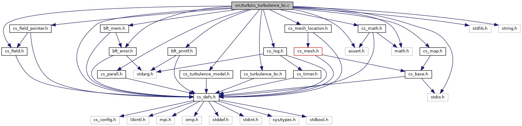
Functions | |
| void | cs_turbulence_model_init_bc_ids (void) |
| Initialize turbulence model boundary condition ids. More... | |
| void | cs_turbulence_model_free_bc_ids (void) |
| Free memory allocations for turbulence boundary conditions ids. More... | |
| void | cs_turbulence_bc_ke_hyd_diam (double uref2, double dh, double rho, double mu, double *ustar2, double *k, double *eps) |
Calculation of  , ,  and and  from a diameter from a diameter  and the reference velocity and the reference velocity  for a circular duct flow with smooth wall (use for inlet boundary conditions). More... for a circular duct flow with smooth wall (use for inlet boundary conditions). More... | |
| void | cs_turbulence_bc_ke_turb_intensity (double uref2, double t_intensity, double dh, double *k, double *eps) |
Calculation of and  from a diameter , a turbulent intensity from a diameter , a turbulent intensity  and the reference velocity for a circular duct flow with smooth wall (for inlet boundary conditions). More... and the reference velocity for a circular duct flow with smooth wall (for inlet boundary conditions). More... | |
| void | cs_turbulence_bc_inlet_hyd_diam (cs_lnum_t face_id, double uref2, double dh, double rho, double mu, double *rcodcl) |
| Set inlet boundary condition values for turbulence variables based on a diameter and the reference velocity for a circular duct flow with smooth wall. More... | |
| void | cs_turbulence_bc_inlet_turb_intensity (cs_lnum_t face_id, double uref2, double t_intensity, double dh, double *rcodcl) |
| Set inlet boundary condition values for turbulence variables based on a diameter , a turbulent intensity and the reference velocity for a circular duct flow with smooth wall. More... | |
| void | cs_turbulence_bc_inlet_k_eps (cs_lnum_t face_id, double k, double eps, double *rcodcl) |
| Set inlet boundary condition values for turbulence variables based on given k and epsilon values. More... | |
| void | cs_turbulence_bc_set_uninit_inlet_k_eps (cs_lnum_t face_id, double k, double eps, double *rcodcl) |
| Set inlet boundary condition values for turbulence variables based on given k and epsilon values only if not already initialized. More... | |
| void | cs_turbulence_bc_rij_transform (int is_sym, cs_real_t p_lg[3][3], cs_real_t alpha[6][6]) |
Compute matrix  used in the computation of the Reynolds stress tensor boundary conditions. More... used in the computation of the Reynolds stress tensor boundary conditions. More... | |
Base turbulence boundary conditions.
| void cs_turbulence_bc_inlet_hyd_diam | ( | cs_lnum_t | face_id, |
| double | uref2, | ||
| double | dh, | ||
| double | rho, | ||
| double | mu, | ||
| double * | rcodcl | ||
| ) |
Set inlet boundary condition values for turbulence variables based on a diameter and the reference velocity for a circular duct flow with smooth wall.
Set inlet boundary condition values for turbulence variables based on a diameter and the reference velocity for a circular duct flow with smooth wall (use for inlet boundary conditions).
We use the laws from Idel'Cik, i.e. the head loss coefficient  is defined by:
![\[ |\dfrac{\Delta P}{\Delta x}| = \dfrac{\lambda}{D_H} \frac{1}{2} \rho U_{ref}^2 \]](form_102.png)
then the relation reads  .
.  depends on the hydraulic Reynolds number
  and is given by:

![\[ \lambda = \dfrac{64}{Re} \]](form_107.png)

![\[ \lambda = \dfrac{1}{( 1.8 \log_{10}(Re)-1.64 )^2} \]](form_109.png)
 , we complete by a straight line
![\[ \lambda = 0.021377 + 5.3115. 10^{-6} Re \]](form_111.png)
From , we can estimate and  from the well known formulae of developped turbulence
| [in] | face_id | boundary face id |
| [in] | uref2 | square of the reference flow velocity |
| [in] | dh | hydraulic diameter |
| [in] | rho | mass density  |
| [in] | mu | dynamic viscosity  |
| [out] | rcodcl | boundary condition values |
| void cs_turbulence_bc_inlet_k_eps | ( | cs_lnum_t | face_id, |
| double | k, | ||
| double | eps, | ||
| double * | rcodcl | ||
| ) |
Set inlet boundary condition values for turbulence variables based on given k and epsilon values.
| [in] | face_id | boundary face id |
| [in] | k | turbulent kinetic energy |
| [in] | eps | turbulent dissipation |
| [out] | rcodcl | boundary condition values |
| void cs_turbulence_bc_inlet_turb_intensity | ( | cs_lnum_t | face_id, |
| double | uref2, | ||
| double | t_intensity, | ||
| double | dh, | ||
| double * | rcodcl | ||
| ) |
Set inlet boundary condition values for turbulence variables based on a diameter , a turbulent intensity and the reference velocity for a circular duct flow with smooth wall.
| [in] | face_id | boundary face id |
| [in] | uref2 | square of the reference flow velocity |
| [in] | t_intensity | turbulent intensity |
| [in] | dh | hydraulic diameter |
| [out] | rcodcl | boundary condition values |
| void cs_turbulence_bc_ke_hyd_diam | ( | double | uref2, |
| double | dh, | ||
| double | rho, | ||
| double | mu, | ||
| double * | ustar2, | ||
| double * | k, | ||
| double * | eps | ||
| ) |
Calculation of , and from a diameter and the reference velocity for a circular duct flow with smooth wall (use for inlet boundary conditions).
Both and  are returned, so that the user may compute other values of and
  with .
We use the laws from Idel'Cik, i.e. the head loss coefficient is defined by:
then the relation reads . depends on the hydraulic Reynolds number and is given by:
, we complete by a straight line
From , we can estimate and from the well known formulae of developped turbulence
![\[ k = \dfrac{u^{\star 2}}{\sqrt{C_\mu}} \]](form_113.png)
![\[ \varepsilon = \dfrac{ u^{\star 3}}{(\kappa D_H /10)} \]](form_114.png)
| [in] | uref2 | square of the reference flow velocity |
| [in] | dh | hydraulic diameter |
| [in] | rho | mass density |
| [in] | mu | dynamic viscosity |
| [out] | ustar2 | square of friction speed |
| [out] | k | calculated turbulent intensity |
| [out] | eps | calculated turbulent dissipation |
| void cs_turbulence_bc_ke_turb_intensity | ( | double | uref2, |
| double | t_intensity, | ||
| double | dh, | ||
| double * | k, | ||
| double * | eps | ||
| ) |
Calculation of and from a diameter , a turbulent intensity and the reference velocity for a circular duct flow with smooth wall (for inlet boundary conditions).
![\[ k = 1.5 I {U_{ref}}^2 \]](form_563.png)
![\[ \varepsilon = 10 \dfrac{{C_\mu}^{0.75} k^{1.5}}{ \kappa D_H} \]](form_564.png)
| [in] | uref2 | square of the reference flow velocity |
| [in] | t_intensity | turbulent intensity |
| [in] | dh | hydraulic diameter |
| [out] | k | calculated turbulent intensity |
| [out] | eps | calculated turbulent dissipation |
Compute matrix used in the computation of the Reynolds stress tensor boundary conditions.
We note  the Reynolds Stress tensor in the global reference frame (mesh reference frame) and
  the Reynolds stress tensor in the local reference frame (reference frame associated to the boundary face).
 is the change of basis orthogonal matrix from local to global reference frame.
is a 6 by 6 matrix defined such that:
![\[ \vect{R}_{g,\fib} = \tens{\alpha} \vect{R}_{g,\centip} + \vect{R}_{g}^* \]](form_569.png)
where symetric tensors have been unfolded as follows:
![\[ \vect{R}_g = \transpose{\left(R_{g,11},R_{g,22},R_{g,33}, R_{g,12},R_{g,13},R_{g,23}\right)} \]](form_570.png)
.
 should be computed as a function of
  as follows:
![\[ \tens{R}_{g,\fib}=\tens{P}_{lg}\tens{R}_{l,\fib}\transpose{\tens{P}_{lg}} \]](form_573.png)
with
![\[ \tens{R}_{l,\fib} = \begin{bmatrix} R_{l,11,\centip} & 0 & c R_{l,13,\centip}\\ 0 & R_{l,22,\centip} & 0 \\ c R_{l,13,\centip} & 0 & R_{l,33,\centip} \end{bmatrix} + \underbrace{\begin{bmatrix} 0 & (1-c) u^* u_k & 0 \\ (1-c) u^* u_k & 0 & 0 \\ 0 & 0 & 0 \end{bmatrix}}_{\vect{R}_l^*} \]](form_574.png)
and  .
.
Constant c is chosen depending on the type of the boundary face:  at a wall face,
  at a symmetry face.
| [in] | is_sym | Constant c in description above (1 at a symmetry face, 0 at a wall face) |
| [in] | p_lg | change of basis matrix (local to global) |
| [out] | alpha | transformation matrix |
| void cs_turbulence_bc_set_uninit_inlet_k_eps | ( | cs_lnum_t | face_id, |
| double | k, | ||
| double | eps, | ||
| double * | rcodcl | ||
| ) |
Set inlet boundary condition values for turbulence variables based on given k and epsilon values only if not already initialized.
| [in] | face_id | boundary face id |
| [in] | k | turbulent kinetic energy |
| [in] | eps | turbulent dissipation |
| [out] | rcodcl | boundary condition values |
| void cs_turbulence_model_free_bc_ids | ( | void | ) |
Free memory allocations for turbulence boundary conditions ids.
| void cs_turbulence_model_init_bc_ids | ( | void | ) |
Initialize turbulence model boundary condition ids.
Initialize turbulence model boundary condition ids.
 1.8.16